Guitars of Love
![]()
Building a 'Super DI'
Mains / phantom / battery powered
Unbalanced to balanced, and balanced to unbalanced converter
|
This is a really good project for anyone wanting a bells and whistles DI that doubles as a door stop on windy nights.... Seriously though, it is very handy device in any pro audio workshop, PA or recording situation.
The project is a combination of the now deleted DI kit from companies such as Altronics Distributors and JAYCAR, part of the old EA DI kit from the '80s, and a bit of myself. If you wish to build this now, you'll have to do it all on vero board. It utilises the power section of the old EA kit to sort phantom power and 9V battery, with it's momentary LED indicators designed to come on for a few seconds and then fade out to save power. I have also added a mains power capability which gives the best fidelity because of the higher operating voltage. All three power sources can be plugged in and the unit just sorts the best one via blocking diodes. The original kit is useless on phantom power because the ICs specified drain too much current. I fixed this by using TL064 8 pin twin op-amps which draw a miniscule 600uA at idling. Also on the original kit PCBs there is a design boo boo with the phase of the output. 'hot' and 'cold' are the wrong way round, and this is easily corrected during wire-up to the O/P sockets. |
|
|
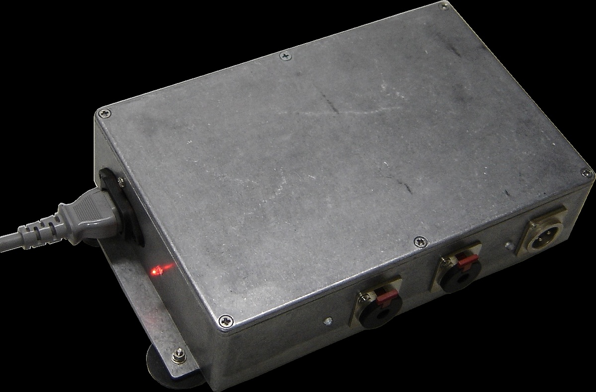
At right is the latest mock-up made to the project spec but using locking TRS sockets as well. The small vero board on the back side is for the -15dB pad attenuation circuit. You can see a higher res picture here: or here including the I/P and O/P functions:The sturdy locking sockets have the disadvantage that they earth the circuit through the chassis so the ground 'UP' switch only works if the earths (0 V) are disconnected from the jack sockets.
|
|
|
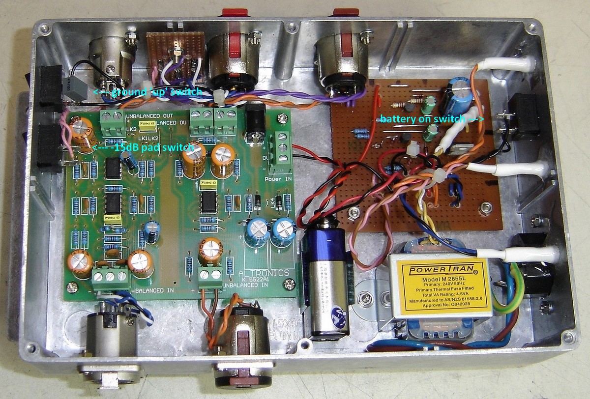
The rocker switch on the right side near the power board is to switch the battery on (not something that would get a lot of use). |
|
|
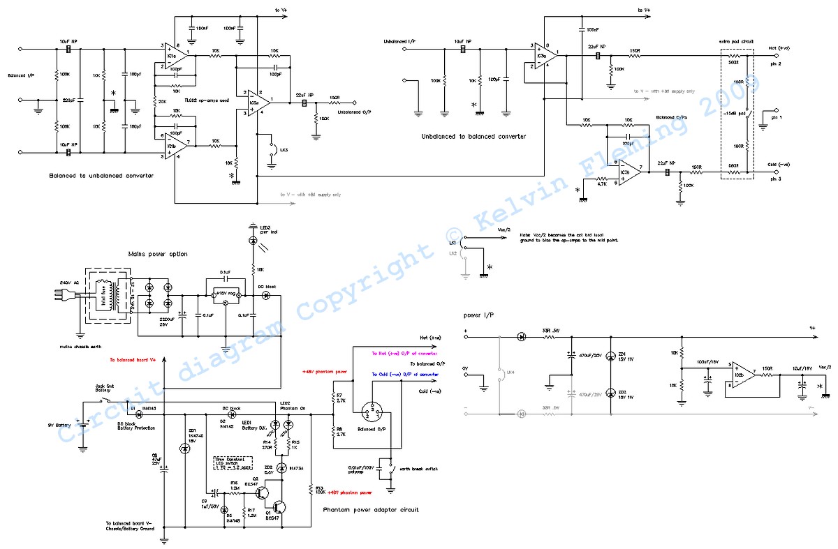
At right is the overall schematic including the Altronics / Jaycar kit and the power adaptor board from EA. Click on the image for the full res pdf. Note: There is a mistake on this circuit relating to what is 'HOT' and 'COLD'. The indication on the board of +ve or 'hot' is in fact -ve phase , or 'cold', so these need to be reversed when connecting the XLR & TRS output sockets. |
|
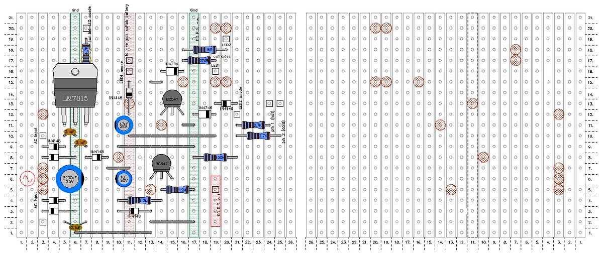
| At right is the Vero board design for the power adapter board. Just follow this to the letter and scallop out the appropriate breaks in the copper. Click on pic for the full hi res pdf one. |
|
|
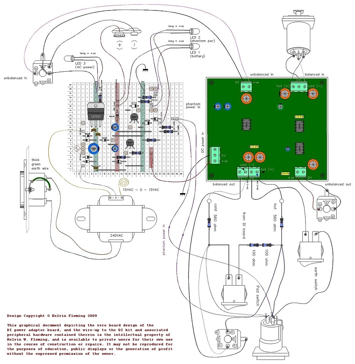
At right is the wire up connection diagram for the DI. Click on the image for the full res pdf.This is the easiest way of understanding where all the connections go to the power control vero board. The extra bits for -15dB pad are best put on a small board like the pictures at the bottom of this page. Note: There is a mistake on this circuit relating to what is 'HOT' and 'COLD'. The indication on the board of +ve or 'hot' is in fact -ve phase , or 'cold', so these need to be reversed when connecting the XLR & TRS output sockets. I have also replaced the small 78L15 regulator with the bigger and much more reliable LM7815 TO-220 regulator. |
|
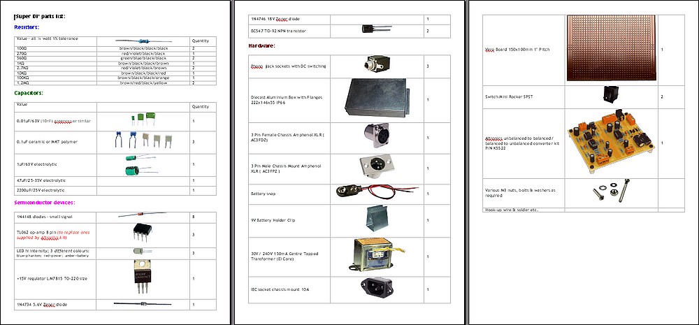
| The parts list on a pdf doc. |
|
|
At right is the vero board for regulating whichever power source is used. It automatically switches between 9V battery, phantom power and mains power. |
|
|
... |
|
|
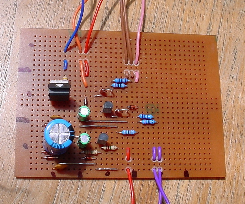
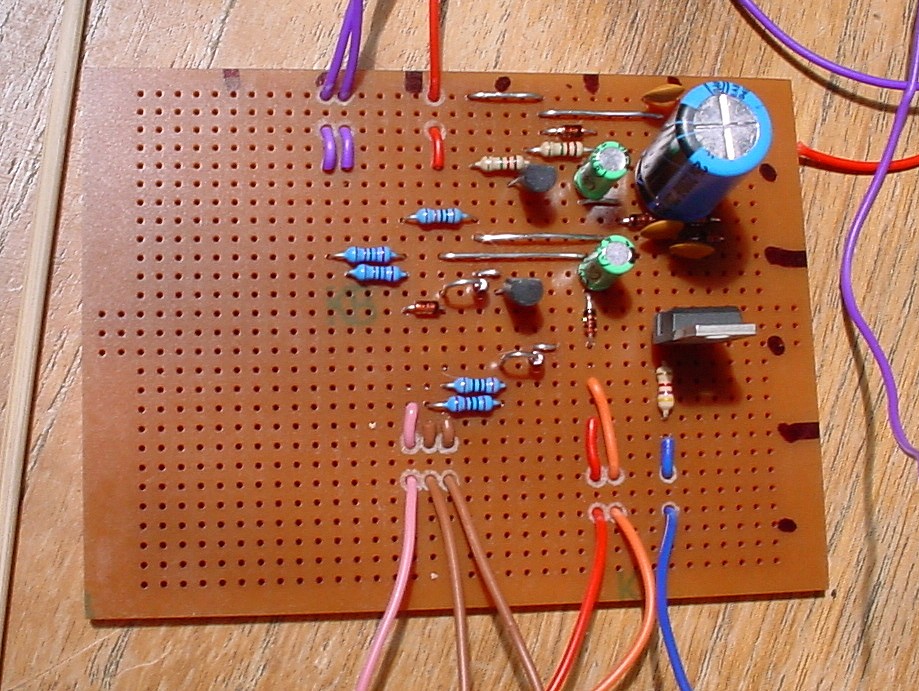
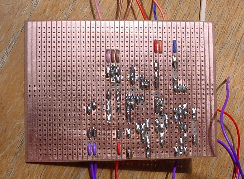
At right; detailed pictures of the vero board after parts soldered in place. The copper breaks are scalloped out with a 5/32 drill bit with a rubber band wrapped around as a handle.
All the hookup wires are threaded through the board by just drilling 1/16th holes where convenient (without disrupting the circuit) and feeding the wire up from the underside to the appropriate hole. This makes for highly reliable wiring. If the wires are just directly soldered in from the top they easily fatigue and break off whilst assembling. Many of the track breaking scallops can be used for this dual purpose. |
|
|
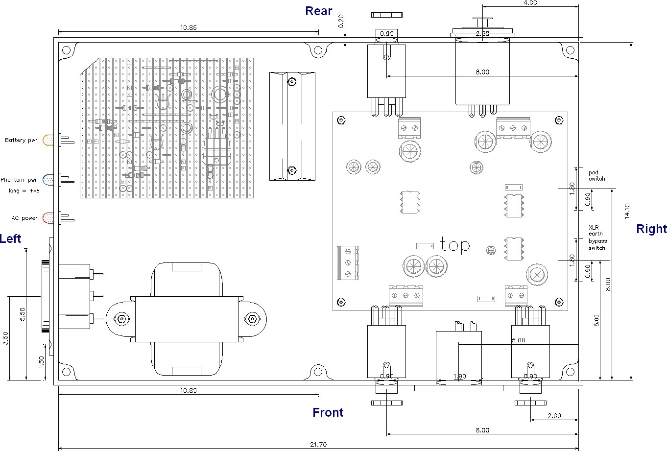
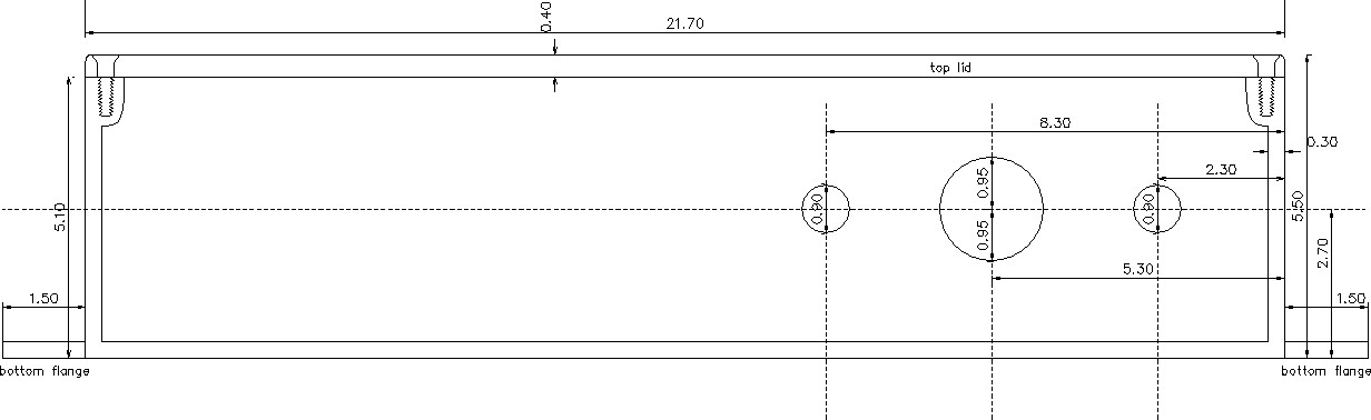
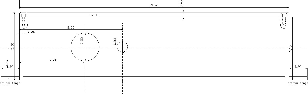
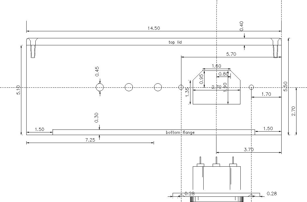
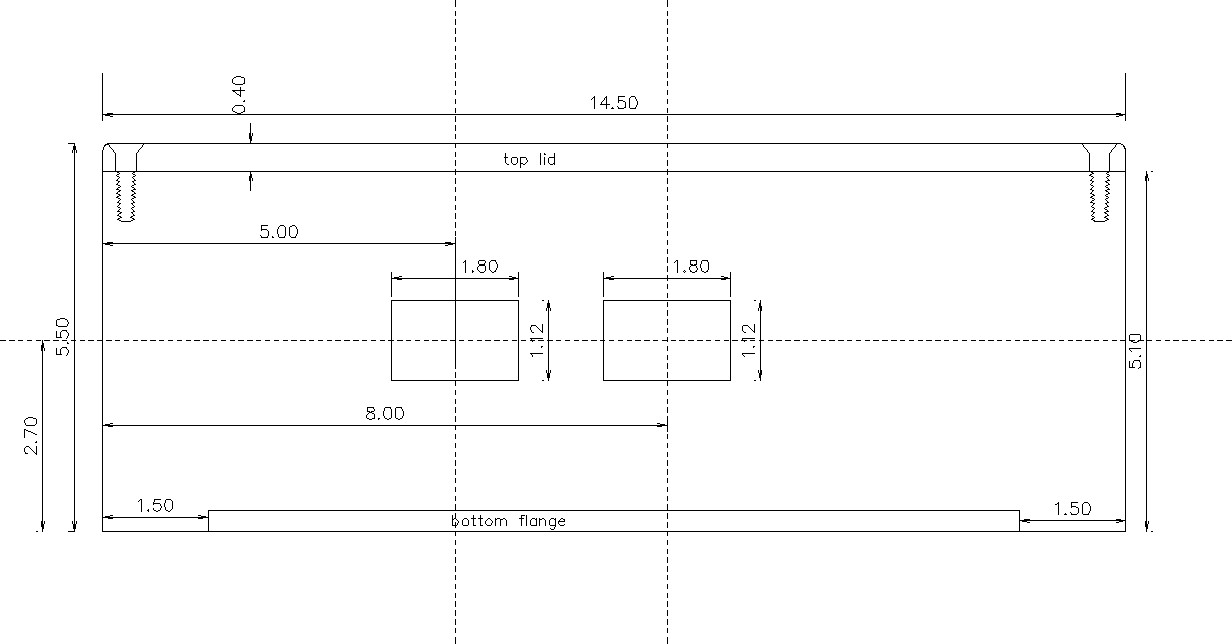
At right: are plans for the case which is an Altronics part number: H0429 This is the exact design used in my electronics classess using the switching 6.3mm jack sockets. If you scroll down to the bottom of the page you see photos of the project as built by one of my students. Diecast Aluminium Box With Flanges 222x146x55 IP66 H0429 $36.95 |
|
|
Front layout: |
|
|
Rear layout |
|
|
Left side layout: |
|
|
Right side layout |
|
|
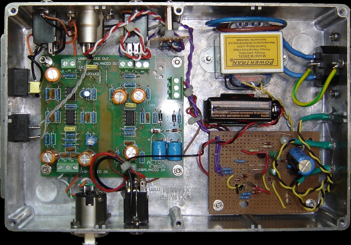
The one pictured at right was built by a student in class using the switching insulated TRS sockets for batter power and earth isolation. The extra bits for -15dB pad are best put on a small board like the one indicated in the pictures at right. |
 |
|
The one pictured at right was built by a student in class. The extra bits for -15dB pad are best put on a small board like the one indicated in the pictures at right. |
|
|
|
|
| kelvin@guitars-of-love.com |