Guitars of Love
![]() ...my original, one of a kind ... guitar pre-amp
...my original, one of a kind ... guitar pre-amp
My original 'GuitFET'... is a pre-amp device with overdrive capability using all discrete single-ended class 'A' circuitry. It's a velvety sounding pre with not a hint of transistor harshness; an ambitious project at the time when I was studying electronics in '93 - '94, it took a couple of years to get it working to my satisfaction. I decided if this one died before I do, I'd have to make another one! This I have done and it works well (scroll down for details)
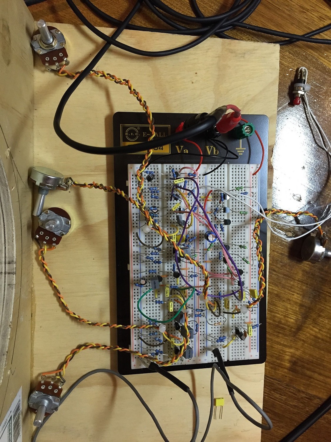
I built this device because I was never happy with standard OD pedals being used as pre-amps with my clean sounding Marshall combo. I had an Ibanez Tube Screamer, and a DOD 250 pre/OD and a Boss OD-1 etc etc and to me they sounded like distortion pedals. I wanted a classy pre-amp to give me the warmth and flexibility and drive but with clarity. Originally I built a valve one whilst I was in college studying practical electronics, but realised it's much more difficult to tweak because you have to solder and unsolder parts. It occured to me that a depletion FET could be biased with a resistor on the source (the equivalent of a cathode in a 12AX7), and produce the same effect when overdriven. After a large time experimenting on a breadboard, I built this one. I tweaked it for years making subtle changes, and I have to say, it's the best sounding guitar pre-amp I'd ever used at that point.
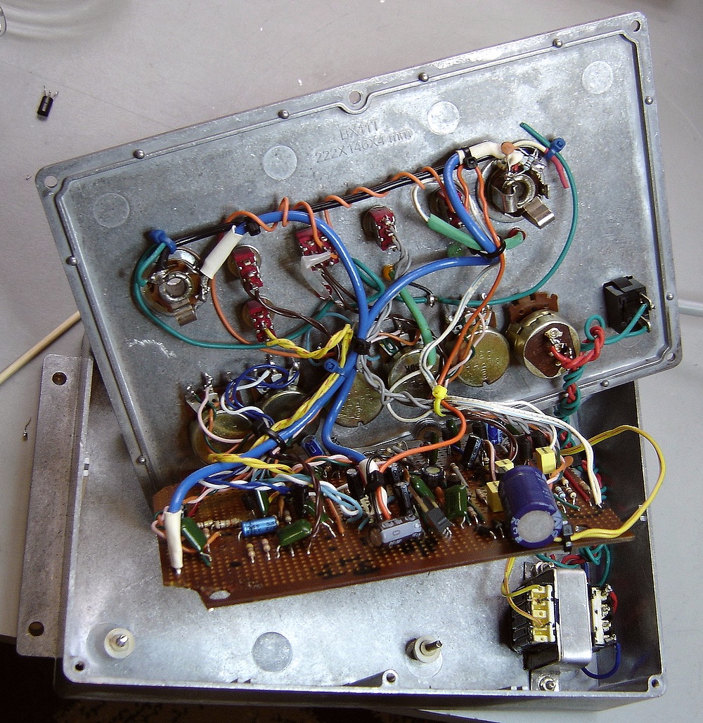
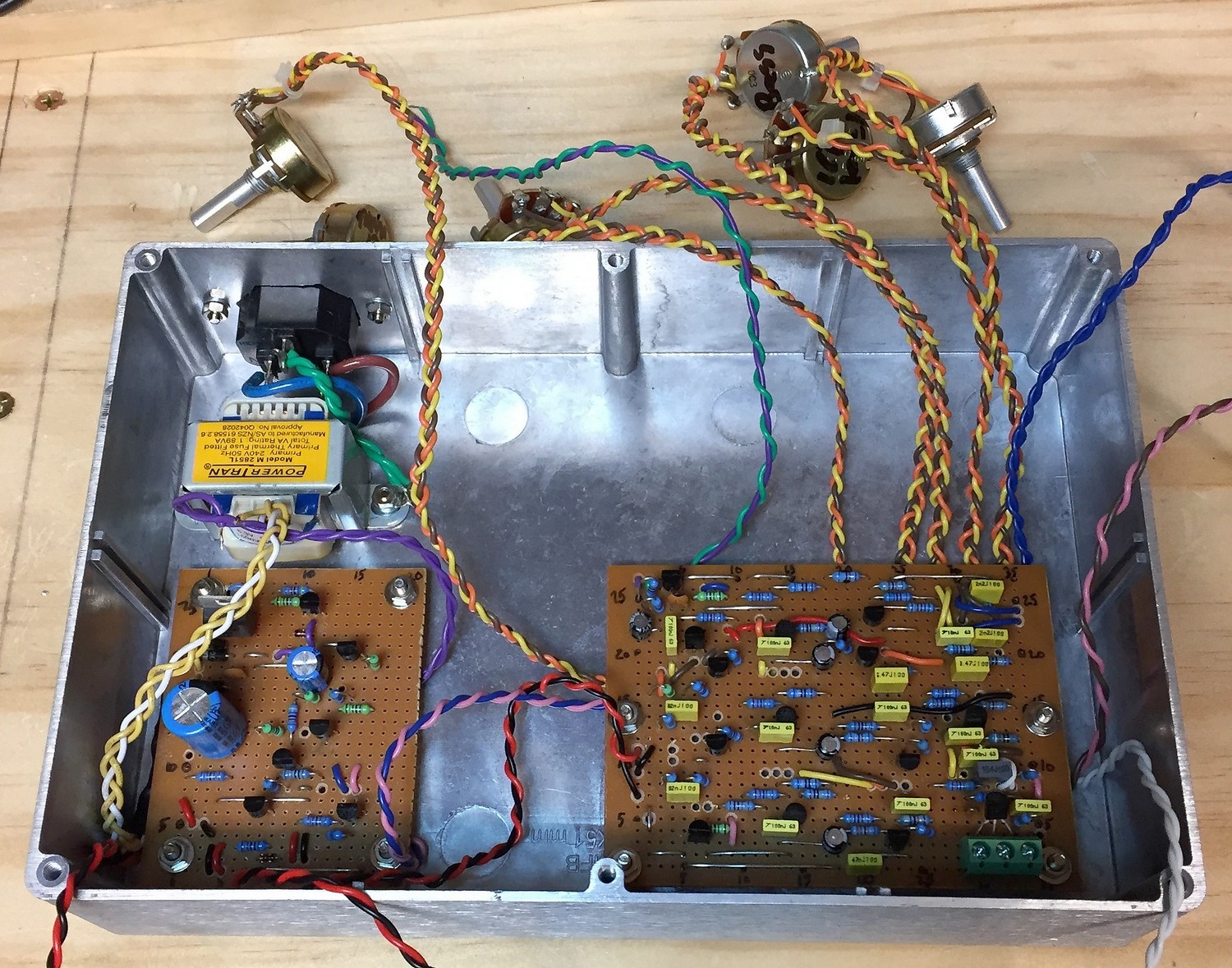
Below are some pics of the insides, and as you can see, it is quite an affair and pretty hard to work on. Looking at it now - I can barely believe I got it going as well as I did given the complexity and the ad lib way I built it. I have made many little changes over the years and every time I do I inevitably cause more problems (such as frayed hookup wires) because of the way it was constructed. Recently I had to change a leaky electrolytic cap which was damaging the board, and I also found a bizarre connection where the 9V rail was tied to the wiper of the treble pot!?
|
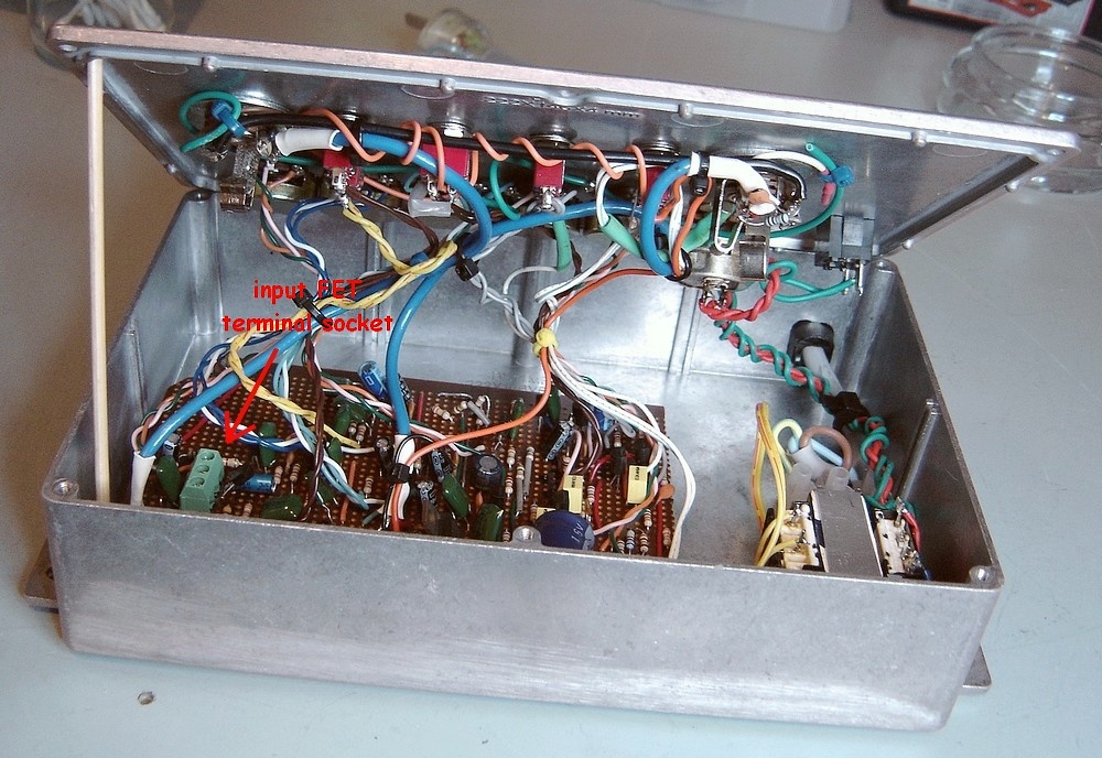
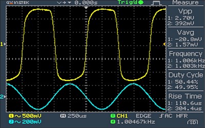
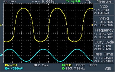
The more recent GuitFET I've built is even better, It uses a depletion FET on the high Z input, and utilizes bass / treble tone controls before two separate depletion FET OD stages which are switched electronically. It has a level control for the input to the tone/drive section as well, and a volume balance control for the 1st & 2nd OD stages, giving more control over characteristics. There is also a master volume output control of course. The original one is extremely versatile because of the fact that the input can be controlled, as well as the level to the twin over driving FET stages. Either the 1st, or 2nd FETs can be switched in, or both together for maximum OD. It goes from a gentle twangy breakup to full shred. The tone controls were purposely configured to emulate a valve amp with limited frequency response, being reasonably flat from around 50Hz to 18KHz - a bit like a good quality valve stereo amp from the '60s. I didn't have room for a true bypass footswitch and use it mostly to set the tone on my old Marshall to mimmick a smaller valve amp being played at a moderately overdriven state. You can see hi res pics of the insides here: I have had to replace the input FET on two occasions due to sporadic voltage conditions in a house I lived in for a while. The FET is very sensitive to stray voltages and static, and requires care. Consequently I have installed a terminal block to allow easy replacement of the input FET by just screwing a new one in should it fail - just like changing a valve. I see nothing wrong with this concept. FETS can suffer partial degradation if damaged and loose gain before failing completely. Semiconductor devices are not the forever devices people believe. In my considerable experience of servicing, I have found that transistors can be subject to long term degradation, particularly early PNP signal ones. If you click on the oscilloscope image below you can see a range of waveforms from the GuitFET in various modes of drive. Also to the right of that one is an image link to a comprehensive testing of my Diason single ended class 'A' guitar amp. It uses a 6CA7 (EL34) to produce 11 watts RMS of power at clipping. It's been modded to include a low power setting of around a watt, and several levels of adjustable negative feedback in the output stage, ranging from none at all, to almost total. If you compare the GuitFET and the Diason class 'A' waveforms you will see some remarkable similarities. |
|
|
|
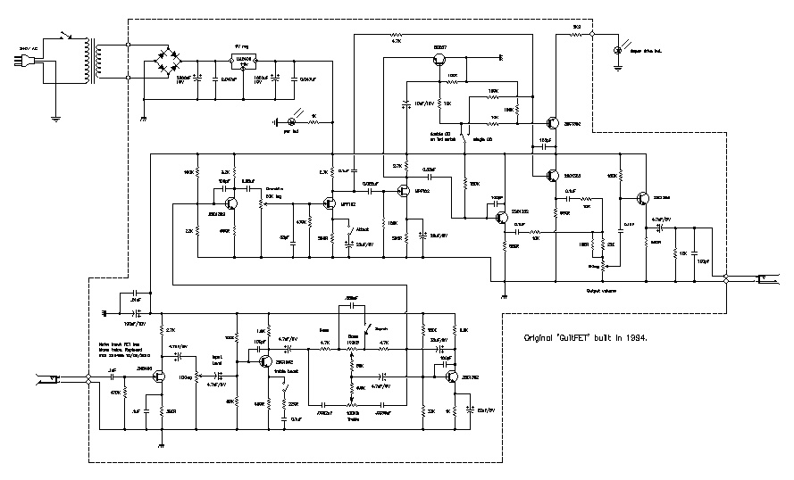
You can download a pdf copy of the original schematic here:

Download a pdf of the newly completed & updated schematic here:
NOTE: Initially I had a hum problem with the PS but this has been fixed. It's preferable to use low ESR caps on the raw DC input from the diode bridge. 2 x 3300uF/25V low ESR electrolytic caps to give a better quality 9V DC.
A pdf of the Vero board design for the new one here here:. The power supply and bistable switch are on a separate board; the PS board being half the size of the main board after trimming.
The new one sounds great and very close to the original, but has a lot more tone control variation, and a bit more drive. It also has electronic switching between the mild overdrive and the double FET high OD with the aid of a momentary switch operating a separate bistable switch circuit, and two separate OD sections; one FET and the other with two FETS operating independently.
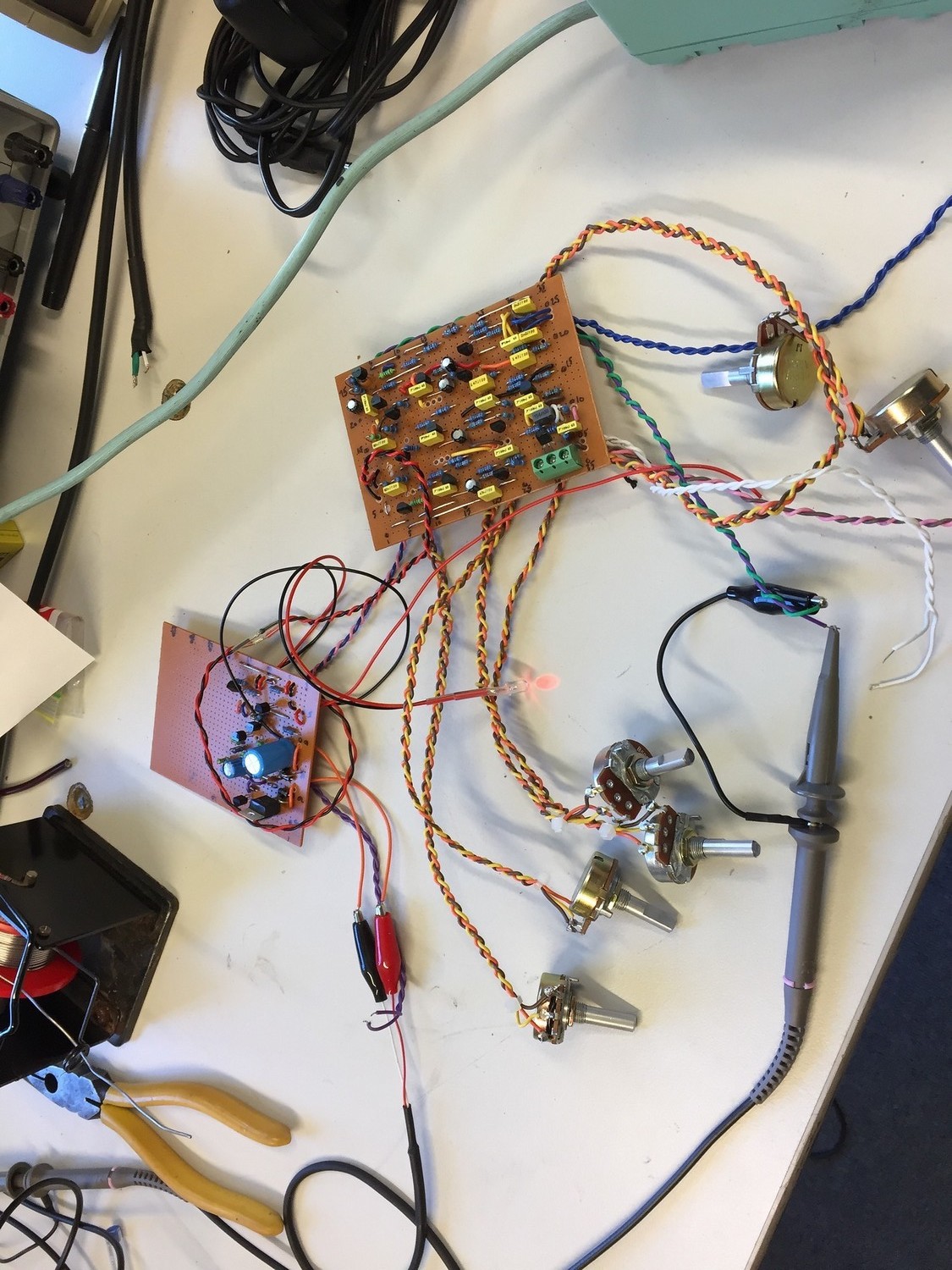
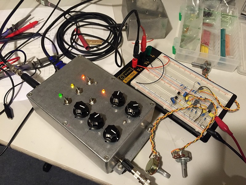
Testing the boards for full functioning after completion. Everything worked 1st time!
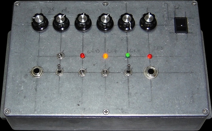
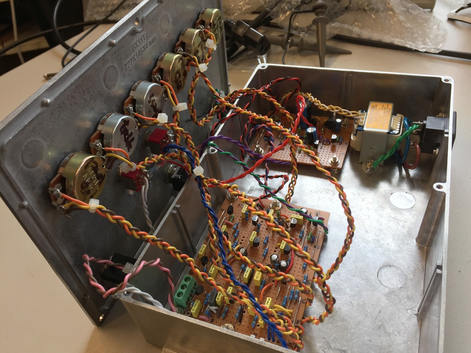
Assembling the circuit boards in the case after initial testing. Now it's a matter of placing the pots in the appropriate sequence 'I/P level / BASS / TREBLE / OD LEVEL / OD MATCHING AND VOLUME OUT'. There will also be a treble boost switch; the momentary foot switch for OD selection and the mid-boost which bypasses the feedback in the bass tone circuit giving extra drive.
All assembly complete. The picture depict the PS section before the addition of extra DC filter caps at the front end of the PS.
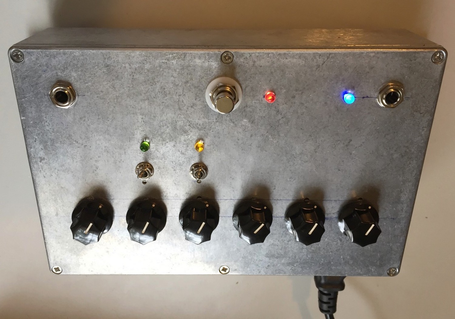
All assembly complete. The final device with the extra PS filter caps gaffered to the top. I also recommend using an oversized power transformer to facilitate a smoother DC supply - around 300mA

The finished unit ...
My first attempt at building a new one was dissapointing, and even though I thought I had replicated all the values of the orignal circuit, sounded nothing like the old one. Some remedial work has inproved the sound but it is a far cry from my old one: basically a failure!
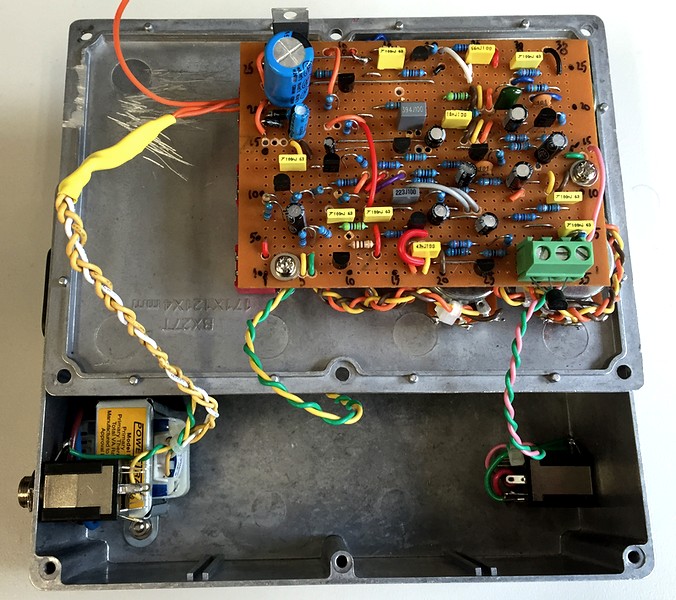
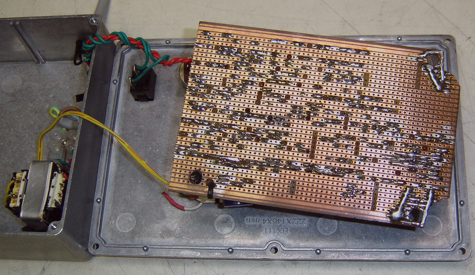
Below are photos of the original GuitFET.
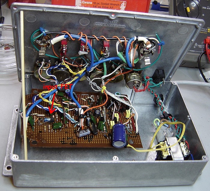
I had no plan for the board layout of this. I just ad-libbed.

You can see the broken corner of Vero board. This poor thing has been in and out so many times to make changes I had to patch the board with solder wick.
In the pictures at the bottom you can see where I have installed a PCB mount terminal board to facilitate changing the FET at the input. I thought "why not ..." that's what they did in the valve days.