Guitars of Love
![]()
|
Sick of dozens of crappy 'wall warts' around the place... Build a regulated 9 volt guitar FX pedal supply |
 |
|
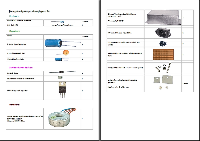
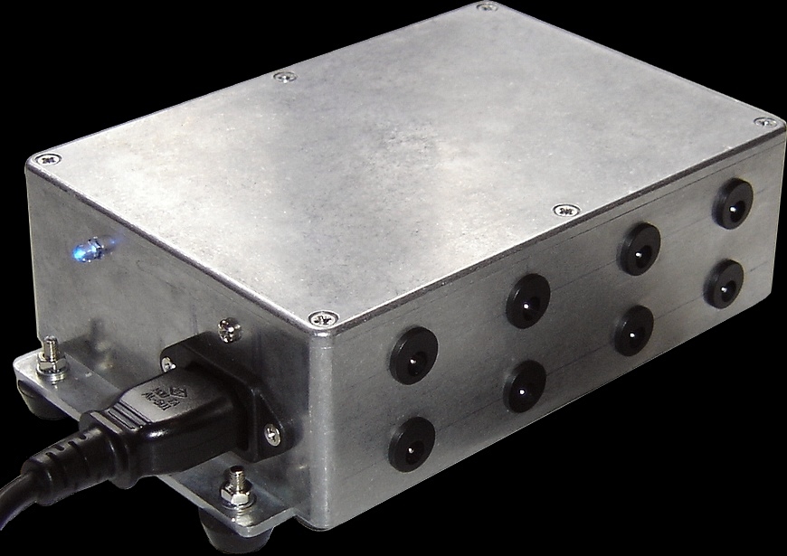
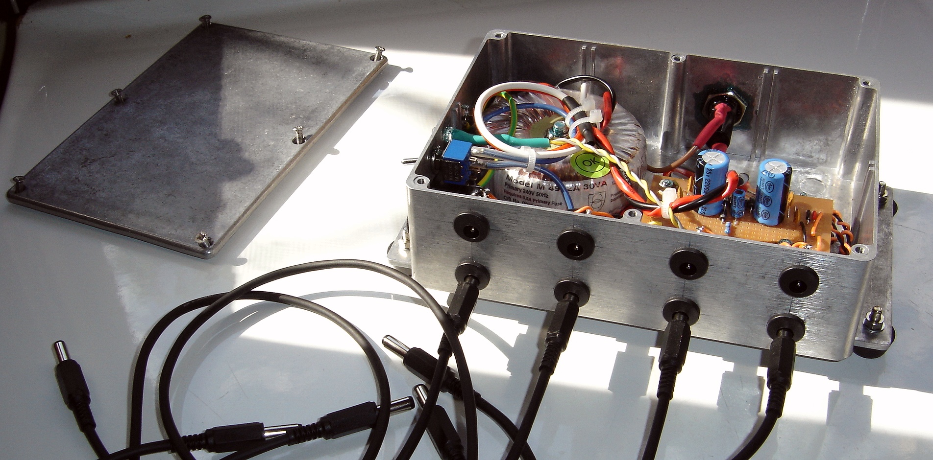
I call this 'Version 6'. I knocked this up as a custom job for a customer and took some photos along the way. Once again it produces exactly 9 volts DC without the hum and noise of a typical 'Wall Wart'. The transformer used in this one is a 30VA toroidal type rated at 12V - 0 - 12V @ 1.25 amps, with one side not used, or 2.5 amps with both windings paralleled, and the 9V is produced via a 7809 3 pin TO220 regulator. It's way over-engineered for the apps but I like solid chunky stuff that can take the bumps. It's built inside an IP66 industrial standard Altronics case (P/N H0427) The parts list is basically the same except it used 8 x DC sockets all along one side. This baby will run any number of pedals!
You can download the parts
list with on a pdf with pictures. Just click on the pic below:
|
|
|
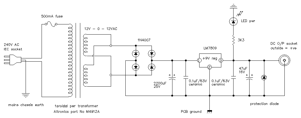
At right is the basic schematic for the circuit board inside the unit. It is a simple mains transformer supplying around 18 VAC to a bridge rectifier (4 x diodes) and a large electrolytic filter capacitor just before the 9 volt 3-pin regulator. After the regulator comes another smaller storage cap; a 3300 ohm (3.3K) resistor to the power indicator LED; and the output DC sockets which are the same as on FX pedals (male). The very small 0.1uF (100 nano Farad) caps are to reduce HF noise that may be generated by the diodes and the regulator. The +ve voltage is connected to the outer rim off the socket (like all FX pedals), but is isolated from the alloy metal case so as not to cause any problems with shorting out. The case is solidly earthed to the mains earth however to make doubly sure of safety. |
|
|
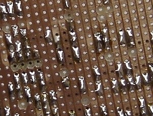
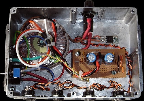
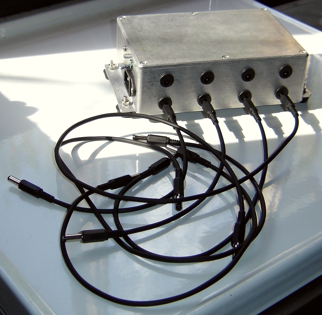
At right shows the connections to the transformer and from the board to the 9V regulator attached to the alloy case. The hookup wire should be routed under the board and threaded through the board as shown in the photographs below: Connections to FX pedals will require a male-to-male 2.1mm DC plug lead which could then be paralleled to several other leads. On this one I have 8 DC sockets. The copper breaks are scalloped out with a 5/32 drill bit with a rubber band wrapped around as a handle.
All the hookup wires are threaded through the board by just drilling 1/16th holes where convenient (without disrupting the circuit) and feeding the wire up from the underside to the appropriate hole. This makes for highly reliable wiring. If the wires are just directly soldered in from the top they easily fatigue and break off whilst assembling. Many of the track breaking scallops can be used for this dual purpose.
|
|
|
Inside the completed supply: Later on I included an ON / OFF switch at the request of the customer. It also sports an external fuse, and double capacitor filtration on the primary DC input totaling 4,400uF. With a light load it will keep pedals running for several seconds if power is interrupted! |
|
|
|
 |
|
|
| kelvin@guitars-of-love.com |